Installation

All electrical work must be done with the power off by
trained HVAC technicians and to all governing codes.
ECM Motors
- ECM motors are designed for continuous operation
- ECM motors should not be turned on and off by by switching the line voltage to the motor.
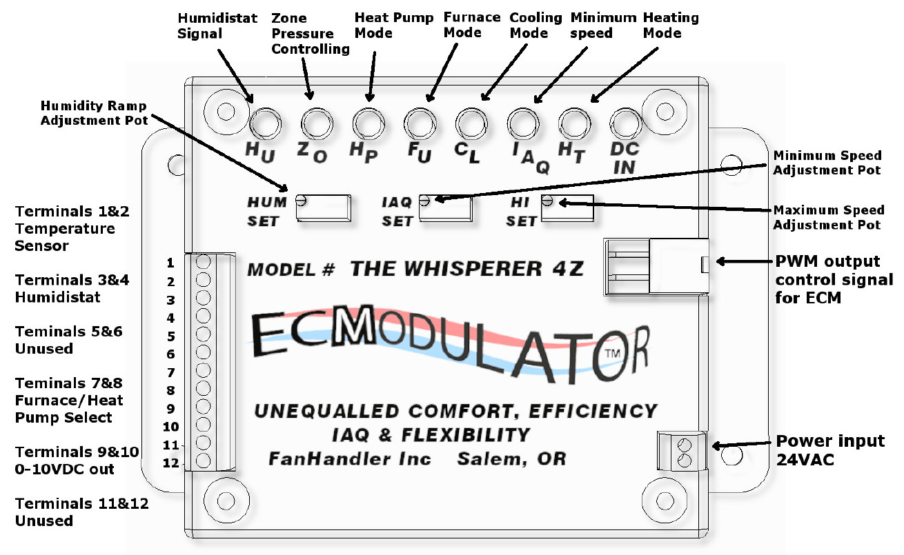
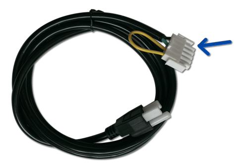
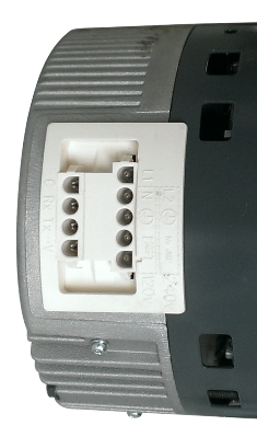
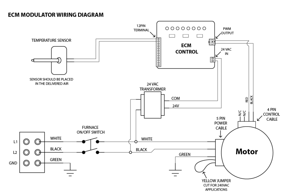
They should only be activated by switching the low voltage to the ecMModulator. - The motor’s high voltage supply terminates in a five position (socket) plug that plugs into the motor’s 5-pin socket.
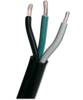
- The 3-prong plug at the opposite end from the high voltage wire is ready for 115/120 vac (standard household current) voltage.
- For higher voltages, see the instructions below.
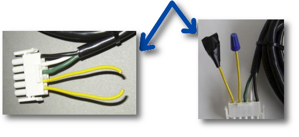
are configured for 115/120 volt applivation.
cut the Yellow wire as shown. Then
wire nut the ends of the wires. Next,
tape over the wire nuts to further secure
them.
white to L1 @ L2.
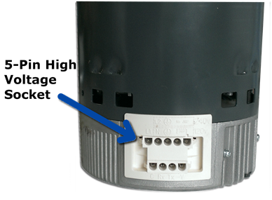
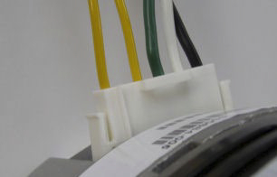 NEXT, PLUG THE 5-PIN PLUG
INTO THE FIVE-PIN HI VOLTAGE
SOCKET.
 |
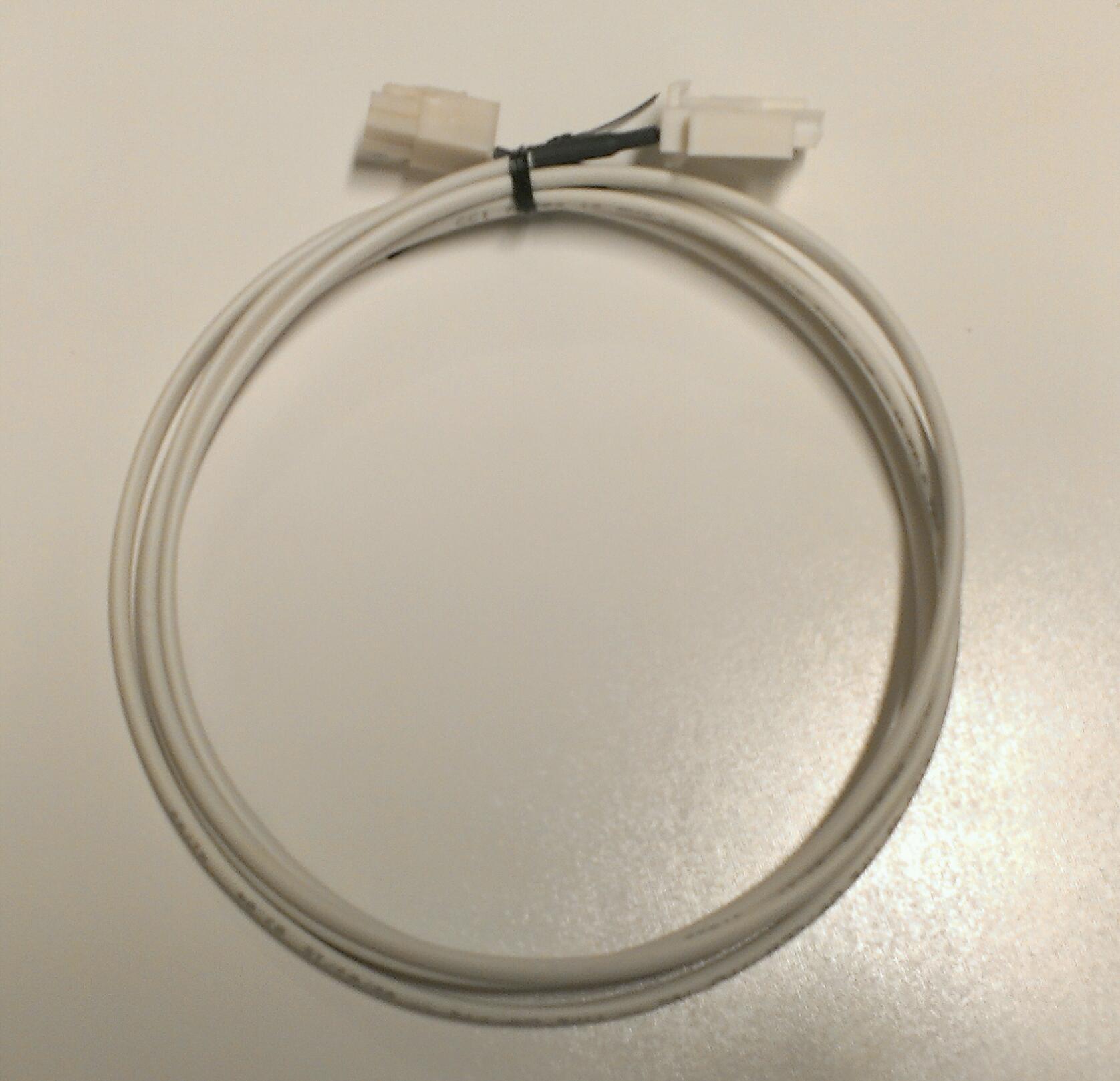
Plug one end of the low voltage
Pulse Width control cable into the
ecMModulator and the other end
into the motor’s 4-pin socket.
 |
 |
CONTROL MODES
The following control modes are some of the obvious strategies that can be employed.The ecMModulator can be used for a wide variety of applications and we can program the
ecMModulator to suit a wide variety of specialized applications.
TRUE FURNACE MODULATION OF HEAT, COOL & IAQ
 |
Before getting into the different modes available for the ecMModulator, you might want to get an overview of the basic operation by viewing this video.
|
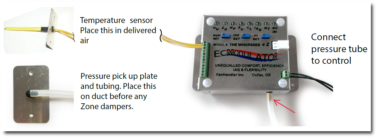
AIR CONDITIONING
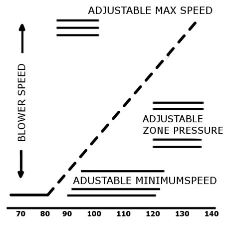
ROCK SOLID PRESSURE CONTROL
BY ELIMINATING BYPASS DUCTS AND DUMP ZONES
pot clockwise will increase the maximum duct pressure and counter clockwise will decrease the
maximum duct pressure. 2 full turns will approximately equal 0.1" wc. ecMModulator 4 Z controls
are shipped with a factory duct pressure setting of about 0.3” wc. Before you begin setting the
pressure re-move the temperature sensor wire from the control (top terminal). This will drive the
blower up to and slightly past the present pressure setting speed. Wait while the blower’s speed
settles before changing the pressure setting. If you want to control from pressure alone, then just
remove the temperature sensor and leave it off. A step by step procedure for adjusting the
pressure is listed below.
2. For a higher pressure, turn the screw on the HI SET pot clockwise.
3. For a lower pressure, turn the screw on the HI SET pot counterclockwise.
4. If the pressure is close to what you want, turn the pot slowly about a quarter turn at a time to
give the motor and control time to adjust. A rough calculation is that about two turns will change
the pressure about 0.1” wc.
5. When you are at or above the programmed pressure setting, the ZO light will be on.
6. If you overshoot the adjustment and wish to reverse the setting you made, you can figure that
it takes about 1/4 turn to take up the slack in the pot’s clutch before you will notice a change.
8 Once you achieve the pressure setting you want, reconnect the sensor wire.
CAUTION - THE TRANSDUCER IS A VERY SENSITIVE AND EXPENSIVE DEVICE. DO NOT BLOW INTO THE TUBING OR SUBJECT IT TO HIGHER THAN ACCEPTABLE SYSTEM PRESSURES!!!!!!!!
FREQUENCY DRIVES
Problem: Motor is not spinning
|
Cause |
Solution |
|
No Power to control |
First check for lights on the control. If there are no lights, you are not getting power to the control. Use a multi meter to check for 24VAC at the input terminal. |
|
Pressure limit set too low or pressure tube is crimped (Model 4Z only) |
Take note of which lights are on. If the red ZO (zone) light is on there may be a crimp in the pressure tube or it is pinched somewhere. Check the pressure tubing and fix anything that looks like it maybe blocking the control from receiving proper air flow. If there is nothing obstructing the air flow to the control and the zone light is still on, the pressure limit may be set too low. Adjust it up by turning the high speed pot clockwise 1 to 2 full turns and see if the light goes off. If it goes off your motor should come on and begin to pick up speed.
|
|
Motor is not getting power |
First check that the high voltage going to the motor is a constant voltage source capable of handling the current draw of your motor. Also check that the power connector is fully seated into the motor and that the yellow jumper on the power connector is intact for 120V operation and clipped for 240V operation. If 240V was applied to the motor with the yellow wire intact then your motor may be blown. Please contact FanHandler for a replacement.
|
|
Motor is not receiving a signal from the control |
You can check that the control is outputting a signal with a multimeter. Set the multimeter to the 20Vdc range and check for voltage across terminals 9 and 10. If the voltage measured is between 0.7Vdc and 10Vdc, the control is putting out a signal to the motor. Check that the control signal cable is properly seated into both the control and the motor. If the cable is properly connected and the motor still doesn’t spin, there may be a break in the cable. Check that you are getting a signal at the motor end of the cable with your multimeter. If you are getting a voltage less then 0.7Vdc your minimum speed is set too low. Adjust the minimum speed.
|
Problem: Motor spins but will not ramp up speed with temperature
|
Cause |
Solution |
|
Improper placement of temperature sensor |
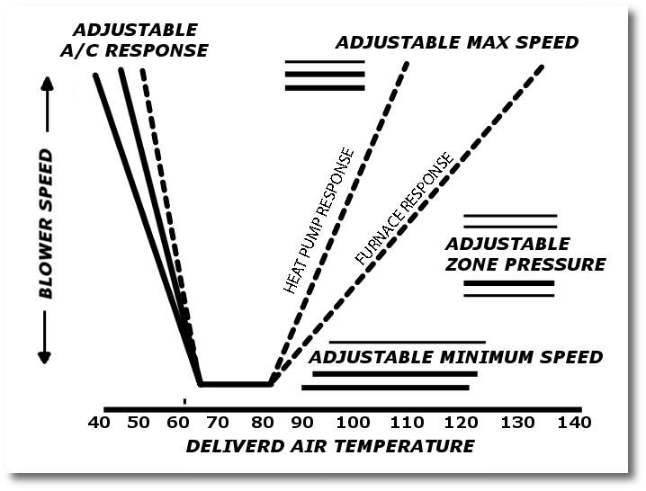
Check the temperature at the sensor to make sure you are getting the temperature that you expect. Remember the fan speed is proportional to the temperature seen by the control. The fan should start to pick up speed at 78 degrees on the heating side and 62 degrees on the cooling side. |
|
Pressure setting too low |
Check to see if the Zone light is on. If so, try adjusting the pressure setting. If the zone light is not on, it could be the control trying to limit the pressure (it’s just not quite fast enough for the light to come on). Try adjusting the HI SET pot clock wise. |
Problem: Motor spins and picks up speed but not fast enough
|
Cause |
Solution |
|
Improper placement of temperature sensor |
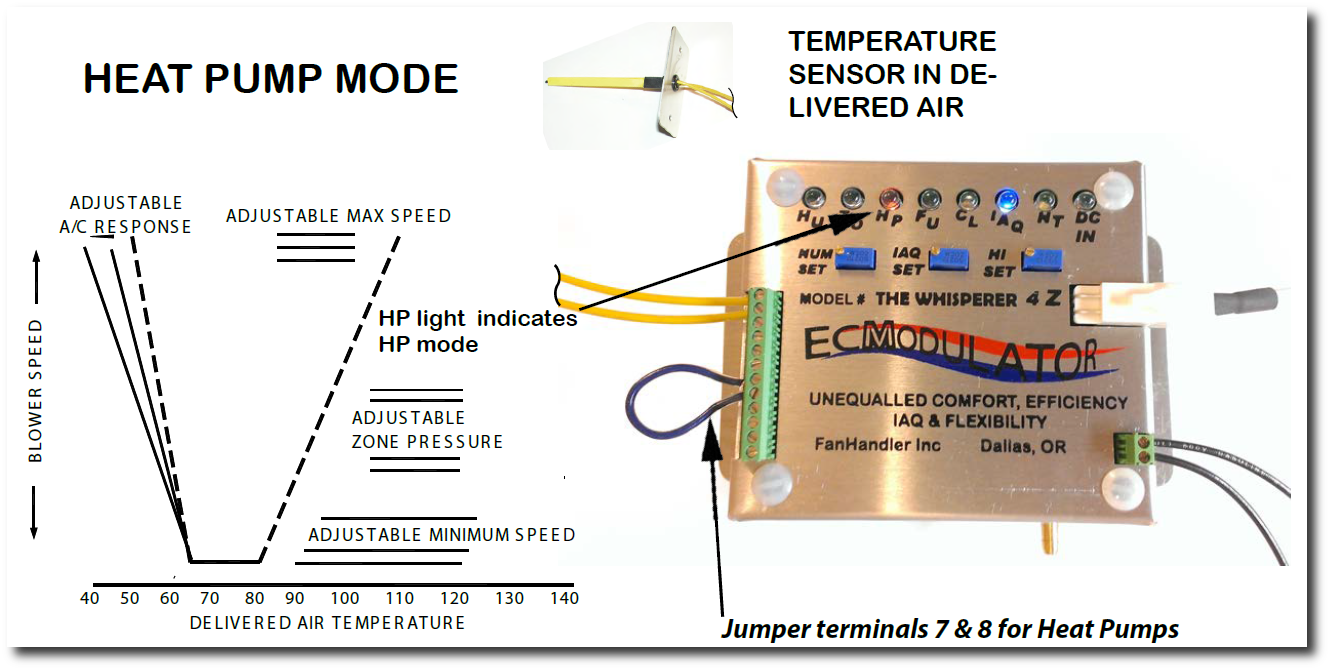
Check the temperature at the sensor to make sure it is getting an accurate temperature reading. On the heating side the fan will start to pick up speed at 78deg and hit top speed at 115deg in heat pump mode and 130deg in furnace mode. On the cooling side the fan will begin to pick up speed at 62 degrees and hit top speed at 54degrees. (For more details please refer to sensor placement guide). |
Problem: Motor ramps with temperature but doesn’t react as zones open and close
|
Cause |
Solution |
|
Improper placement of the pressure plate (Model 4Z only) |
Make sure the pressure pickup plate is placed before all dampers and located in a part of the duct that has good air flow. You want to avoid places where there may be an air pocket; such as, right after a corner. Check that the pressure tube is properly connected and not crimped or pinched. |
Problem: Speed ramps up fine in heating but not fast enough in cooling
|
Cause |
Solution |
|
Improper placement of temperature sensor |
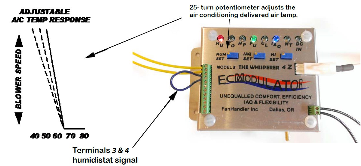
Check the temperature at the sensor to make sure it is getting an accurate temperature reading. (Optional) If you are not using a humidifier or dehumidifier, you can adjust the cooling ramp with the humidity pot (HUM pot). First place a jumper across terminals 3 and 4. This will put the control into humidity mode. By default, the HUM pot is turned down about 9 turns for a speed drop of about 100 rpm. You will need to adjust this by turning the pot clockwise 9 full turns, to bring the ramp back to center. From here you can continue turning the HUM pot clockwise to begin to raise the cooling ramp. Turning counter clockwise will lower the cooling ramp. |
Problem: Speed ramps up fine in cooling but not fast enough in heating
|
Cause |
Solution |
|
Improper placement of temperature sensor |
This is most likely a sensor placement issue. Check the temperature at the sensor to make sure it is getting an accurate temperature reading. (Optional) If this is a furnace application and you want the control to ramp up faster in heating, you can set the control to heat pump mode. In heat pump mode the control will ramp up to full speed quicker on the heating side while leaving the cooling side unaffected. |
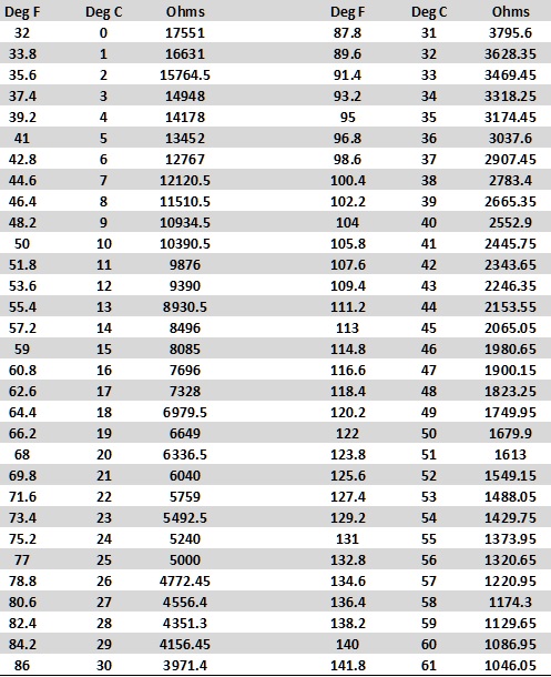
Yellow Sensor Temperature To Resistance Chart